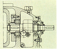
General
Magnetic coupled DICKOW-Pumps of series HZSM / HZSMA are of sealless design. The containment shell forms a closed system with hermetically sealed liquid end. The properties of the integrated side channel stage allows the handling of entrained gas and operation under suction lift conditions.

Applications
Magnetic driven HZSM / HZSMA-pumps are designed to improve plant and personnel safety, especially when handling toxic, explosive or other dangerous liquids which react on contact with the atmosphere. For all these services the containment shell replaces double acting mechanical seals, along with external fluid reservoirs and the necessary control equipment. HZSM / HZSMA-pumps therefore offer exceptional benefits to the chemical, petrochemical and allied industries and fulfill all environment protection rules. Due to the fact that 90% of pump failures are caused by leaking shaft seals, the sealless design increases the availability and reduces maintenance costs. The HZSM-type is used in tank farms, for offloading rail cars and trucks, filling of storage tanks and other applications where priming of empty suction pipes is required. Considering low NPSH-values, gas handling capability and sealless design, the HZSMA-type offers special benefits to liquified gas applications. Typical application is filling of LPG-trucks and rail cars in refineries.
Unit of Measure

Maximum Transmissible Power

N/A 150 kW at 2900 rpm (250 Hp at 3500 rpm)

Maximum Capacity (Flow Rate)

N/A 1000 gpm at 60 Hz

Maximum Head

N/A 1500 ft at 60 Hz

N/A Sleeve bearings
The internal bearings are of the sleeve-type, positioned in the pumpage. Standard material is diamond coated pure Silicon Carbide, highly resistant against corrosion and wear and providing also dry running capability. Internal circulation, pressurized magnet end.
When pump is in operation, it generates eddy currents which heat up the containment shell and the pumpage in the magnet area. This heat is dissipated by internal product circulation. The internal circulation flows from discharge through the magnet area back to the inlet of the last impeller.
The capacity of the cooling flow, together with pressurization of the magnet end, prevents vapourization or flashing of pumpage in this area when handling boiling liquids.


Antifriction bearings
The drive shaft is carried in generously dimensioned antifriction bearings, grease filled for lifetime and protected by radial seal ring against environment. An oil mist or oil bath API-bearing housing is an option. The protection device avoids damage to the containment shell in case of worn out ball bearings.

N/A Balanced thrust loads
The thrust loads of the closed impellers are hydraulically balanced in a way that forces of the impellers are acting in the containment shell direction. These forces will be balanced by the balancing disk.
The front side of the balancing disk is pressurized from the discharge side with the pressure P-sp the rear side is connected with the first pump stage and thus, pressurized with the lower pressure P2. The difference between the constant pressure P2 and the variable pressure P-sp creates a counter force in direction of the suction flange. The value of this reaction force depends on the pressure Psp respectively the variable gap S. That means the balancing disk floats until the forces at impeller and disk are balanced. During operation there is no contact between the rotating SiC-ring in the disk and the stationary SiC-ring in the casing. Suction- and discharge casing


Diffuser, Radial loads
The impellers are centered inside of the diffusers. The diffusers are of multi-flow channel design. Therefore, no radial loads exist on the sleeve bearings.

N/A Construction
The HZSM / HZSMA-pumps are single or multi stage horizontal centrifugal pumps, combined with integrated side channel stage on discharge side, and permanent magnetic coupling. The containment shell forms a closed wetted end and separates the pumped liquid from the atmosphere.

Containment shell
The containment shell is designed as a pressure vessel to separate the pumpage from the atmosphere only. The containment shell is not used as an additional bearing holder. No dynamic stress occurs. The shell is sealed against the atmosphere by a confined gasket.

Magnet coupling
The single elements of the multipolar magnetic coupling are manufactured of a permanent magnet material "Cobalt Samarium - Rare Earth" with unlimited lifetime. The magnets in the internal rotor are completely encapsulated; no contact with liquid occurs.
Energy is transmitted to the hermetically sealed liquid end by a bank of external magnets passing motive force through the containment shell to a bank of internal magnets. Inner and outer magnet rings are locked together by magnetic power and work as a synchronous coupling. The inner magnet ring transmits the required torque directly to the impeller. Overload of the magnetic coupling and slipping will not effect demagnetization. The magnetic drives are designed for electric motors, direct on line starting. Should a subsequent increase of motor power be required, i.e. when installing a larger impeller, the nominal power of the magnetic coupling can be increased accordingly by an additional series of magnets. The maximum drive power is 150 kW at 2900 rpm (250 HP at 3500 rpm).

Suction- and discharge casing
The pump flanges of HZSM-pumps are provided principally in vertical top position to ensure a certain quantity of liquid in the pump which is necessary for priming empty suction pipes and lifting liquid from underground storage facilities. For obtaining low NPSH-value, the suction casing is designed in volute shape.
The HZSMA-pumps - for applications with flooded suction conditions - are provided with suction casings of end suction design to obtain further reduction of NPSH-values.

Suction impeller
For lowering the NPSH-value, the impeller of the first stage is designed as a suction impeller with enlarged impeller eye.

Priming stage
The side channel stage is capable to evacuate the suction line and therefore, to self-prime if initially filled with operating liquid. In the priming phase the side channel pump works as a positive displacement pump. The displacement effect is created by a rotating liquid ring which enters and exits the side channel in a piston fashion during each rotation. This is generated by an interrupter in the side channel which separates suction and pressure area. The piston effect conveys the gas from suction to discharge side. The priming stage works automatically; no auxiliary vent equipment required. When pumping LPG, attention must be paid to gas entrainment by vapor bubbles. In practice, these pumps can pump this liquid-gas mixture without auxiliary device. Due to the increased pressure in the side channel stage, the gas bubbles turn into liquid phase again.

Monitoring
Connection for temperature detection element for containment shell surface temperature is available as standard. Dry running protection and monitoring of ball bearings and containment shell temperature with the patented MAG-SAFE System is highly recommended.